Hello friends
Rright now I am working with induction furnace
as a final year project.
As a part of that I am working on an inverter made up of
H-bridge connection of Power MOSFETs.
Basic connection of an inverter would be as shown in figure
below….
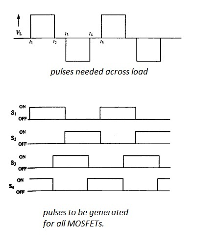
If s1 and s4 are on current through load is positive.
If s2 and s3 are on current through load is negative.
Be careful about simultaneous conduction of s1 and s2 or s3
and s4 if either are conducting simultaneously you will end up with something blown
either it is fuse of lab or your own design..:(
we can come up the short circuit by "crow bar circuit"but that is not discussed here..
Now comes the most challenging work generation of gate
pulses for MOSFETs.
As I know that my load(in future)is
inductive in nature so I have to design it including “zero voltage freewheeling”.
The method of generating these pulses is shown below.
I have used microcontroller (My favorite AVR Atmega 8535 )to generate Ramp wave.
Code to generate ramp
wave of 10 KHz is given below(crystal freq is 16MHz)
include<avr/io.>
#include<delay.h>
void main()
{
DDRB=0xFF;
unsigned char i=0;
while(1)
{
PORTB=i++;
asm("nop");
asm("nop");
}
}
Then the
wave is fed to a comparator, the reference voltage is given with the help of a potentiometer user can adjust it.
after applying these gate pulses to MOSFET (IRF640)we can see the changing direction of current through the load branch...
the codes for generating ramp wave and ISIS Proteus design can be found from here.
that's all for this post friends next I'll post what difficulties i faced in implementing this ISIS design to reality.
feel free to comment


nice information published on this blog this is very interested and meaningful...
ReplyDeleteInverter Manufacturers